The Foton Suspension Mechanism Assembly-2 is a precision upper link and leveling control system designed for Foton tractor three-point hitches. It provides critical implement pitch control, depth stability, and allows for fine adjustment of implement leveling during field operations. Below is a detailed breakdown of its core components:
1. Upper Link Adjustment & Leveling Core:
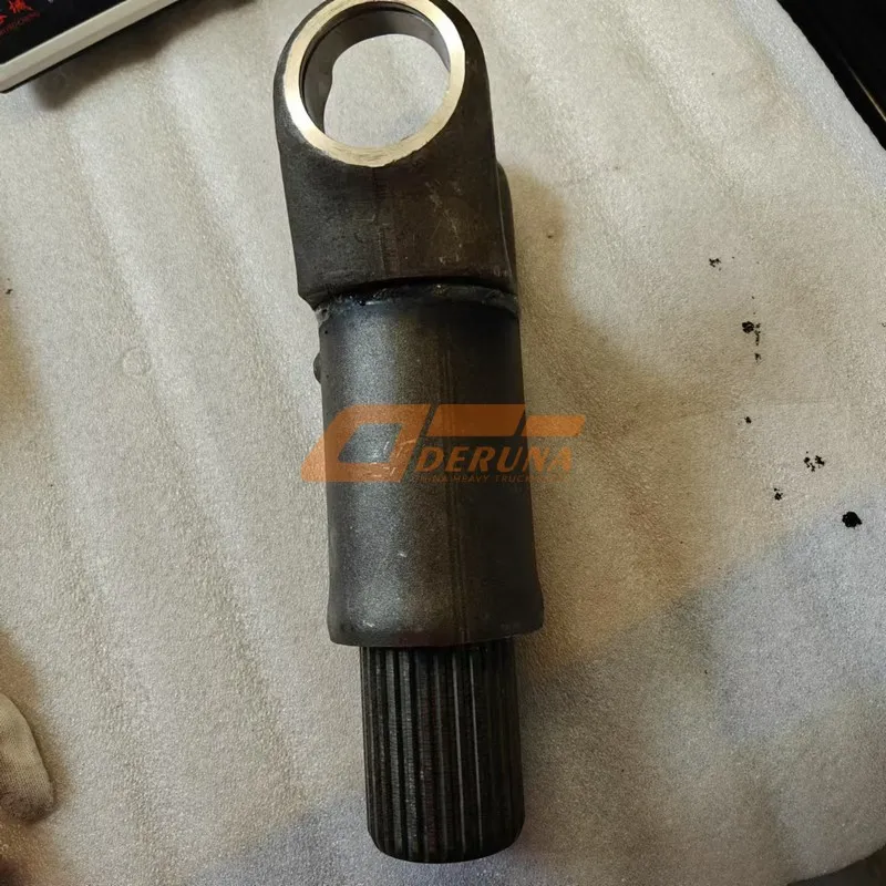
Upper Pull Rod Front Adjustment Rod Assembly: The forward section of the telescopic upper link, featuring threaded adjustment.
Upper Pull Rod Rear Adjustment Rod Assembly: The rear section of the telescopic upper link, connecting towards the implement.
Adjustment Screw Tube: The central tubular component housing the threaded mechanism that links the front and rear adjustment rods. Rotating this tube changes the effective length of the upper link.
Lifting Rod Screw Tube Welded Assembly: Likely synonymous with or integral to the Adjustment Screw Tube, emphasizing its welded construction for strength. This is the primary component turned for length adjustment.
Hexagon Thin Nut (Dual): Specialized nuts (thinner profile) used to lock the Adjustment Screw Tube in place after setting the desired upper link length, preventing unintended rotation during operation. Key for maintaining leveling settings.
2. Linkage & Connection Points:
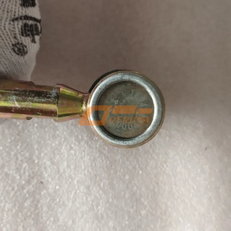
Lifting Rod Upper Connection Fork: The pivotal top connection point attaching the upper link assembly to the tractor’s upper hitch point.
Lifting Rod Upper Connection Pin: The hardened pin securing the Upper Connection Fork to the tractor.
Lower Connecting Fork of Lifting Rod (Dual): The pivotal bottom connection points (likely left and right variants) attaching the upper link assembly to the implement’s hitch point. Ensures articulation.
Lower Connecting Pin of Lifting Rod: The hardened pin securing the Lower Connecting Fork(s) to the implement.
Upper Pull Rod Lock Pin Assembly: A specific pin and locking mechanism potentially used to secure a quick-attach feature or a fixed position within the upper link structure.
3. Mounting & Structural Support:
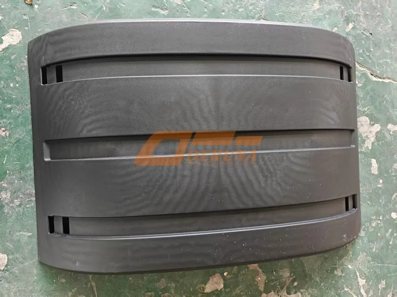
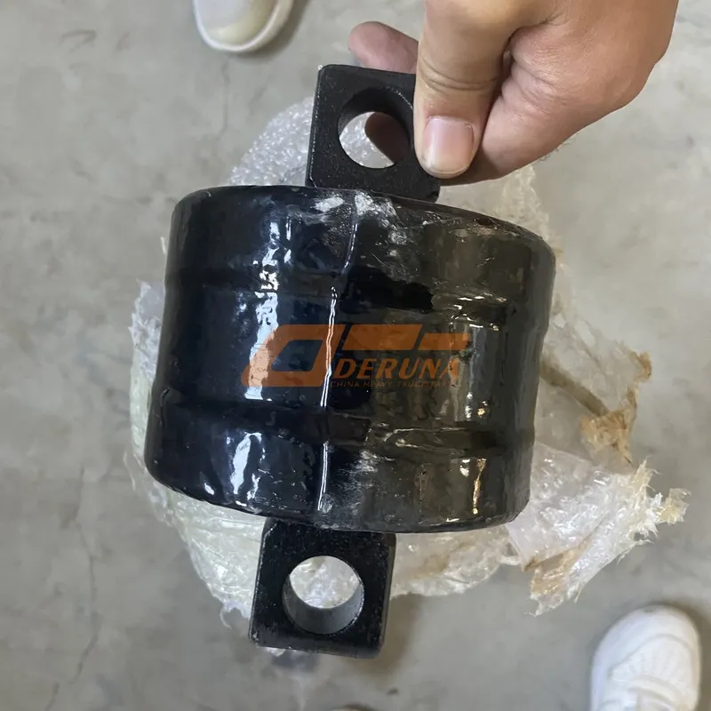
Seat Plate Welded Assembly (Dual): Robust, welded mounting brackets (likely left and right) that provide a secure foundation and pivot points for the upper link assembly on the tractor chassis. Essential for load-bearing.
Fixing Clip: A securing component, potentially used to retain pins, hoses, or other elements near the mounting area.
4. Securing & Safety Components:
Split Pin (Multiple): Cotter pins used as a positive locking device for clevis pins (like the Lifting Rod Upper Connection Pin and Lower Connecting Pin) and potentially nuts, ensuring critical connections cannot vibrate loose.
Flat Washer & Washer (Multiple): Distribute load under nuts and pin heads, prevent surface damage, and ensure secure clamping. Used extensively throughout the assembly.
Type 1 Hexagon Nut: Specifies a particular standard or style of hex nut used for specific fastening points within the linkage or mounting.
Nut: General fasteners used in conjunction with bolts or studs.
The Foton Suspension Mechanism Assembly-2 excels in delivering precise implement leveling and pitch control. Its defining feature is the threaded Adjustment Screw Tube / Lifting Rod Screw Tube Welded Assembly, easily rotated via its exposed tube profile and securely locked with Hexagon Thin Nuts for fine-tuning implement attitude. The robust Seat Plate Welded Assemblies provide a solid foundation, while the Upper and Lower Connecting Forks with their hardened Pins ensure reliable articulation. The extensive use of Split Pins and Washers guarantees critical connections remain secure under vibration, making this assembly vital for maintaining consistent working depth (e.g., for plows, harrows) and transport stability on demanding terrain.
Product Parameters of Foton Suspension Mechanism Assembly-2
Please leave your inquiry and your phone. We will give you feedback within 12 hours.
Our operators are busy. Please try again later
Have you got question? Write to us!
This chat session has ended
WhatsApp us
ONLINE MESSAGE
If you have any questions, please feel free to leave us a message. We will respond within 12 hours! Become our customer and we will provide you with catalog services for free.